
Provided by: |
The fireplace is an American tradition. In pioneer days, fireplaces were used for cooking, were essentially the only source of heat, and were the focal point for family and public gatherings. Today, even with mechanical heating systems and modern kitchen appliances, the fireplace remains a central feature of the home around which family and friends gather for good times and warm fellowship. Concrete masonry, due to its inherent properties, is the most versatile building material for the construction of a fireplace.
Non-combustible concrete masonry effectively isolates the fireplace fire from nearby combustible materials such as wood, plastic, and insulation. Due to the mass and thermal properties of concrete masonry, heat is stored in the concrete masonry itself. Thus, heat is not only radiated to the room from the fire, but also from the concrete masonry hours after the fire dies.
Concrete masonry fireplaces are a safe and efficient source of auxiliary heat when properly designed and constructed. Design and construction requirements are prescribed by the local building codes and these requirements should be checked early in the planning stage. The information provided herein is in compliance with the National Fire Protection Association, NFPA, 211 "Chimneys, Fireplaces, Vents and Solid Fuel Burning Appliances."
Regardless of the design, all fireplaces contain essentially the same elements. These elements are a base, combustion chamber, and smoke chamber, as shown in Figure I for a singleopening fireplace.
The base of the fireplace consists of the foundation and extended hearth support. The foundation consists of a concrete footing and concrete masonry foundation walls, as shown in Figure 1, or for slab-on-grade construction, a thickened slab. The minimum building code requirements should be adhered to for the design and construction of the foundation system. The footings typically must be 12 in. in thickness and extend at least 6 in. beyond the fireplace walls on all sides. The foundation walls are normally specified to be 8 in. thick. Void areas are often provided in the base to form an air passageway for external combustion air, an ash pit, or both. Non-essential void areas should be solidly filled with masonry.
Immediately above the foundation walls, support for the combustion chamber and the extended hearth are necessary. The support for the extended hearth may be formed by corbelling the masonry foundation wall, but is usually provided by a poured concrete slab that also supports the combustion chamber. The forming of the concrete slab requires "block outs" for external combustion air dampers and ash drops if there are air passageways or ash pits incorporated into the base of the fireplace. Permanent forming required at the top of the foundation walls must be a non-combustible material. Temporary wood forming is usually required to pour the extended hearth support. The forming should be placed so that the projected slab will meet a doubled wood floor joist, and be such that removal is easily executed.
The concrete slab should be 4-in. thick, reinforced, and capable of resisting thermal stresses resulting from exposure to high temperatures. The slab should be dimensioned to adequately support the extended hearth. The extended hearth must extend at least 16 in. in front of the fireplace face and at least 8 in. beyond the jambs of the fireplace opening for fireplaces with openings that are less than 6 sq. ft. If the area of the fireplace opening exceeds 6 sq. ft., the extension must be 20 in. in front of the fireplace face and at least 12 in. beyond the jambs of the opening.
The combustion chamber consists of the extended hearth, the firebox and surrounding masonry, and the throat. The extended hearth, dimensioned as previously discussed, must be constructed of non-combustible materials. Concrete brick or decorative concrete masonry units may be used to construct the extended hearth. The hearth, or floor of the firebox, must be constructed using fire brick or a similar refractory material. Fire brick must also be used to form the firebox. The fire brick should conform to ASTM C 64 Type G. laid to form a firebox wall thickness of at least 2 in., and be placed using a fire clay mortar conforming to ASTM C 105, medium duty. Type N Portland cement-lime mortars have in some instances been successfully used to lay up both the fire brick and clay or pumice aggregate masonry flue liners. Inasmuch as this mortar is not specifically mentioned in NFPA 211, it may be used only if permitted by the local building code.
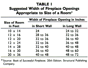
It is imperative that the design and size of the firebox be determined early in the planning stage. The fireplace opening should be based on the room size for aesthetics and also to prevent overheating of the room. Suggested fireplace opening widths are provided in Table 1. Once the opening width is selected, the dimensions of the masonry combustion chamber may be determined by using Table 2.
|
Table 2 - Single-Opening Fireplace
Dimensions, Inchesa
|
|||||||||||||
|
Opening
|
Firebox
|
Throat
|
Smoke Chamber
|
Flue Linerb
|
Steel Angles
|
||||||||
|
Depth
|
Rear Wall
|
Depth
|
Width
|
Height
|
Shelf Depth
|
Width
|
Depth
|
Length
|
Size
|
||||
|
Width
|
Height
|
Width
|
Vertical Height
|
Splayed Height
|
|||||||||
|
24
26 28 30 32 36 40 42 48 54 60 60 72 84 96 |
24
24 24 29 29 29 29 32 32 37 37 40 40 40 40 |
16
16 16 16 16 16 16 16 18 20 22 22 22 24 24 |
11
13 15 17 19 23 27 29 33 37 42 42 54 64 76 |
14
14 14 14 14 14 14 14 14 16 16 16 16 20 20 |
18
18 18 23 23 23 23 26 26 29 29 31 31 28 28 |
8 3/4
8 3/4 8 3/4 8 3/4 8 3/4 8 3/4 8 3/4 8 3/4 8 3/4 13 13 13 13 13 13 |
32
34 36 38 40 44 48 50 56 68 72 72 84 96 108 |
19
21 21 24 24 27 29 32 37 45 45 45 56 61 75 |
12
12 12 12 12 12 12 12 14 12 14 14 14 16 16 |
12
12 12 12 12 12 16 16 16 16 20 20 20 24 24 |
8
8 8 12 12 12 12 16 16 16 16 16 20 20 20 |
36
36 36 36 42 42 48 48 54 60 66 66 84 96 108 |
3 x 3 x 3/16
3 x 3 x 3/16 3 x 3 x 3/16 3 x 3 x 3/16 3 x 3 x 3/16 3 x 3 x 3/16 3 x 3 x 3/16 3 1/2 x 3 x 1/4 3 1/2 x 3 x 1/4 3 1/2 x 3 x 1/4 3 1/2 x 3 x 1/4 5 x 3 1/2 x 5/16 5 x 3 1/2 x 5/16 5 x 3 1/2 x 5/16 |
|
a Adapted from The Donley Brothers
Company, Book of Successful Fireplaces - How to Build Them, 18th
Edition, 1965.
b Flue sizes conform to modular dimensional system. |
|||||||||||||
The steel angle lintel used to support the concrete masonry above the fireplace opening should not be solidly embedded in mortar. If the ends are embedded in mortar, expansion of the lintel upon exposure to the extreme temperatures of the fire may crack the masonry. The use of non-combustible fiberous insulation at the ends of the lintel angle will usually compensate for this expansion and eliminate cracking problems.
The thickness of the concrete masonry enclosing the firebox should be such that there is a minimum of 8 in. of solid masonry between the inside of the firebox and the exterior surface of the fireplace. This 8-in. thickness includes the fire brick used to construct the firebox. The concrete masonry should be isolated from the firebox by a nominal I in. air space. This space will accommodate the differential movement between the fire brick and the concrete masonry. Wrapping the firebox with non-combustible fiberous insulation during construction may help assure that provisions for the expansion of the firebox are maintained.
The throat of the fireplace should be as wide as the firebox and should have a depth of either 83/4 in. or 13 in. depending on the size of the fireplace, see Table 2. The size and position of the throat is critical for proper burning and draft. The throat should be not less than 8 in. above the fireplace opening.
The smoke chamber consists of the damper, smoke shelf, smoke dome and surrounding concrete masonry. The damper, which is critical for proper performance, is placed directly over the throat. The metal damper, like the opening lintel, should not be solidly embedded in mortar. When the fireplace is not in use, the damper should be closed to prevent heat loss. When a fire is started, the damper should be wide open. Once the fire begins to burn readily, the damper should be adjusted to produce more efficient combustion. Allowing the damper to remain wide open greatly reduces the efficiency of the fireplace. For convenience and reasons of safety, a rotary controlled damper that is adjusted with a control on the face of the fireplace is preferred. Poker controlled dampers have a handle projecting down into the firebox. Adjusting poker control dampers usually requires reaching into the firebox.
The masonry constructed above the damper should be supported on a second lintel angle rather than bearing on the damper. This lintel angle must be allowed to expand independently from the masonry and thus should not be solidly embedded in the masonry.
Immediately behind the damper is the smoke shelf. The smoke shelf is necessary in conventional fireplaces to check down drafts. Any down drafts strike the smoke shelf and are diverted upward by the damper assembly. The smoke shelf may be curved to assist this checking of down drafts, but flat smoke shelves perform adequately.
The smoke dome should be constructed so that the side walls and front wall taper inward to form the support of the fireplace chimney. The chimney should be positioned so that it is centered on the width of the fireplace and the back of the flue liner is in alignment with the vertical rear surface of the smoke dome. This configuration funnels the smoke and gases from the fire into the chimney. The walls of the smoke dome should
be of a thickness that provides a minimum of 8-in. of solid masonry between the smoke dome and exterior surfaces. The inside of the smoke dome should be parged to reduce friction and help prevent leakage of gases and smoke. The parge coat should be refractory mortar conforming to ASTM C 105, medium duty.
For ease of construction, a high form damper may be used. The high form dampers are constructed such that the damper, smoke shelf and the entire smoke dome are contained in one metal unit. In addition, fireplace inserts may be used. The inserts not only include the elements of the high form damper, but form the firebox as well. The inserts are placed directly on the firebrick hearth.
The chimney is constructed directly on the smoke chamber. The chimney consists of a flue liner and a chimney wall. The flue liners should be 5/8 in. thick, conform to ASTM 344, (pumice aggregate concrete masonry flue liners are an acceptable substitute), and be set in refractory mortar. The chimney wall should be constructed so that there is at least a 4 in. nominal thickness of solid concrete masonry between the flue liner and any exterior surfaces. The chimney wall should be separated from the flue liners by a nominal l-in. airspace. This will permit the flue liner which contains hot gases and smoke to expand freely without cracking the chimney wall.
The chimney must extend at least 3 ft. above the highest point where it passes through the roof. In addition, the top of the chimney should be at least 2 ft. above any portion of the building that is within 10 ft. of the chimney. These requirements as shown in Figure 2, are for fire safety. Higher chimneys may be required for adequate draft. Good draft is normally achieved if the chimney height is such that the vertical distance from the top of the fireplace opening to the top of the chimney is 15 ft.
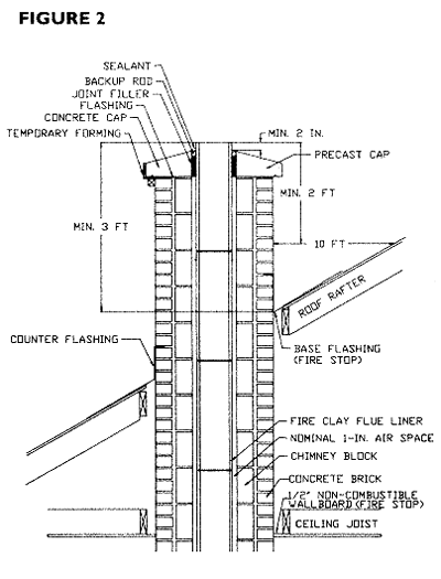
The chimney must be adequately capped to resist water penetration. A mortar wash that is feathered to the edge of the chimney wall is not an adequate cap. The cap should be either cast-in-place or precast concrete, as shown in Figure 2. Metal pan flashing over the top of the chimney will also perform adequately.
Adequate clearance between combustibles and both the fireplace and chimney are important to provide a safe solid fuel burning assembly. NFPA 211 requires that a minimum 2-in. airspace be maintained between the face or sides of the fireplace and any combustibles, excluding trim. Combustible trim, including mantles, should not be within 6 in. of the fireplace opening and if the combustible material projects more than l�-in. from the face of the fireplace, the distance from the opening to the combustible material should be at least 12 in. No combustible materials should be placed within 4 in. of the back wall of the fireplace. These requirements result in clear spaces between the fireplace and combustible framing. These spaces should be firestopped by using galvanized sheet steel that is at least 26 gage, 0.19 in. thick, or a non-combustible sheet material that is not more than �-in. thick.
A 2-in. clearance is required around the perimeter of the chimney wall. This clear space should be firestopped in the same manner as described for fireplaces. If the entire perimeter of the chimney wall is outside the building, excluding soffits or cornices, the clearance between the chimney wall and combustibles may be reduced to 1 in.
The building codes require solid masonry thickness for the construction of fireplaces and chimneys. Although solid concrete masonry units conforming to ASTM C 145, concrete brick conforming to ASTM C 55, and special shaped chimney block are most commonly used for fireplace and chimney construction, hollow units may be used if the cells are fully grouted. Hollow units should conform to ASTM C 90 or C 129. Generally, the concrete masonry units should be installed with mortar conforming to ASTM C 270, Type N. Where high wind loads must be resisted, ASTM C 270 Type S mortar should be used. Other considerations may require the use of ASTM C 270 Type M or S mortars.
The largest improvement in the efficiency of masonry fireplaces involves proper operation. Maintaining efficient fuel consumption, by properly adjusting the damper, is critical. There are several other ways to significantly improve the performance of the concrete masonry fireplace. In the planning stage, position the fireplaces on interior rather than exterior walls. Also, when fireplaces are to be positioned on exterior walls they should be flush with the exterior wall rather than projecting to the outside. Positioning the fireplaces in these preferred locations reduces heat loss when the fireplace is not in operation, and increases the amount of usable radiant heat from the concrete masonry. This increase results from having more of the heated surfaces within the house.
During construction, provisions for improving the efficiency may be incorporated into the concrete masonry fireplace. The efficiency of the fireplace can be significantly improved by introducing external air into the firebox for draft and combustion. This will reduce the amount of already warmed room air that would otherwise be required for draft and combustion. An external combustion air system requires a damper of some sort in the firebox, adequate ducting or air passageways, and a grill or louver at the exterior opening of the system to prevent the entry of animals. The damper should be such that it permits the control of both the direction and volume of the airflow. Introducing excessive cold exterior air into the hot firebox may essentially turn the fireplace into a blast furnace, producing temperatures which are capable of melting grates. These temperatures may have a deleterious effect on the fireplace construction as well. Directional control is also important. The control should be capable of directing air flow towards the back of the firebox so that when down drafts or negative pressures occur, hot ashes or embers are not forced into the room.
During or after construction air circulating grates may be placed in the firebox or glass screens may be placed over the fireplace opening. If glass screens are considered they should be installed in addition to, and not in lieu of, a mesh screen. The glass screens are intended primarily to reduce heat loss by sealing off the fireplace opening when the fireplace is not being operated or when the fire is being allowed to die. The fireplace should not be operated with the glass screens closed, even when external combustion and draft air is being provided. With the glass doors closed and no external air, the fire will be smothered. With the glass doors closed and external draft and combustion air being provided, the potential to create a blast furnace effect is substantially increased. If closed glass screens are desirable during operation, the screens should be equipped with an adjustable damper system, whether or not exterior air is being provided to the firebox. Opening and properly adjusting the damper system, which is usually in the form of an operable grill, may provide sufficient air to the fire to prevent smothering or create the required balance between interior and exterior air being used for both draft and combustion without creating a blast furnace effect.
Combining the information provided here with local building code requirements and good judgment will result in efficient, safe, properly performing concrete masonry fireplaces for both enjoyment and auxiliary heating.