Provided by: |
| Keywords: | allowable stress, anchorage, connectors, wall anchorage, wall ties |
The function of anchor bolts is to transfer loads to the masonry from attachments such as ledgers, sill plates, weld plates, etc. As illustrated in Figure 1, both shear and tension are transferred through anchor bolts in resisting design forces such as uplift due to wind or vertical loads on ledgers due to gravity. The magnitude of these loads will vary significantly. The purpose of this TEK is to assist the designer in determining the proper size, embedment length and spacing of bolts to resist design loads.

Anchor bolts can generally be divided into two categories: embedded anchor bolts which are placed in the grout during construction of the masonry; and drilled-in anchors which are placed after construction of the masonry.
Drilled-in anchors achieve shear and tension (pull out) resistance by means of expansion against the masonry or sleeves, or by bonding with epoxy or other adhesives. The design of drilled-in anchors should be in accordance with manufacturer Æliterature and is outside the scope of this TEK.
Types of Embedded Anchor Bolts
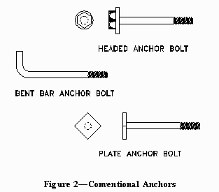
Conventional bolts are available in standard sizes (diameters and lengths) or can be fabricated to meet specific project requirements. The types of conventional anchors most commonly specified are illustrated in Figure 2. These consist of headed, bent bar, and plate anchor bolts.

Headed anchor bolts are usually of either the square or hex-headed variety and are popular due to their wide availability and relatively low cost. Washers are placed against the bolt head for the purpose of enlarging the bearing area and thereby increasing pullout resistance.
Bent bar anchor bolts are currently fabricated in a variety of shapes, since no standard exists governing the geometric properties, with the ōLö and ōJöshapes being the most common. The design provisions in this TEK are based on a bolt with a 90 degree bend and an extension of 1 1/2 bolt diameters. The inside diameter of bend should be at least three bolt diameters.
Plate anchor bolts are fabricated by welding a square or circular steel plate at right angles to the axis of a steel bar. The dimensions of the steel plate (length, width, or diameter) should be at least one inch plus the bolt diameter and the thickness should be at least 0.4 times the bolt diameter.
Applications/Uses
In most new masonry construction, anchor bolts are commonly embedded at:
The design provisions for anchor bolts presented here are excerpts from Building Code Requirements for Masonry Structures (ref. 2) which is referenced by the BOCA National Building Code and Standard Building Code (refs. 1, 3). These provisions are also written into the Uniform Building Code (ref. 5).
Definition:
Connector mechanical device for securing two or more pieces, parts, or members together, including anchors, wall ties and fasteners.
Notations:
Ab = cross-sectional area of an anchor bolt, in.2 (mm2)
Ap = projected area on the masonry surface of a right circular cone
for anchor bolt allowable shear and tension calculations, in.2 (mm2)
ba = total applied design axial force on an anchor bolt, lb (N)
Ba = allowable axial force on an anchor bolt, lb (N)
bv = total applied design shear force on an anchor bolt, lb (N)
Bv = allowable shear force on an anchor bolt, lb (N)
db = nominal diameter of anchor bolt, in. (mm)
fÆm = specified compressive strength of masonry, psi (MPa)
fy = specified yield stress of steel for reinforcement and anchors,
psi (MPa)
lb = effective embedment length of plate, headed or bent anchor bolts,
in. (mm)
lbe = anchor bolt edge distance measured from the surface of an anchor
bolt to the nearest free edge of masonry, in. (mm)
5.14 Anchor Bolts Solidly Grouted in Masonry
5.14.1 Test design requirements
Except as provided in Section 5.14.2, anchors shall be designed based on the
following provisions.
5.14.1.1 Anchors shall be tested in accordance with ASTM E 488 under stresses
and conditions representing intended use except that at least five tests shall
be performed.
5.14.1.1 Anchors shall be tested in accordance with ASTM E 488 under stresses
and conditions representing intended use except that at least five tests shall
be performed.
5.14.2 Plate, headed and bent bar anchor bolts
The allowable loads for plate anchors, headed anchor bolts, and bent bar anchor
bolts (J or L type) embedded in masonry shall be designed in accordance with
the provisions of Sections 5.14.2.1 through 5.14.2.4.
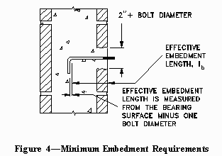
5.14.2.1 The minimum effective embedment length shall be 4 bolt diameters, but
not less than 2 in. (51 mm).
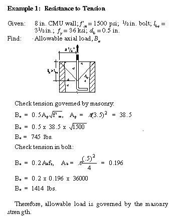
5.14.2.2 The allowable load in tension shall be the lesser of that given by
Eq. (5-1) or Eq. (5-2).
Ap = p lbe2 (5-1)
Ba = 0.2Abfy (5-2)
(a) The area Ap shall be the lesser of Equation 5-3 or Equation 5-4. Where the projected areas of adjacent anchor bolts overlap, p of each bolt shall be reduced by one half of the overlapping area. That portion of the projected area falling in an open cell or core shall be deducted from the value of p calculated using Equations 5-3 or 5-4.
Ap = p lb2 (5-3)
Ap = p lbe2 (5-4)
(b) The effective embedment length of plate or headed bolts, lb, shall be the length of embedment measured perpendicular from the surface of the masonry to the bearing surface of the plate or head of the anchor bolt.
(c) The effective embedment length of bent anchors, lbe, shall be the length of embedment measured perpendicular from the surface of the masonry to the bearing surface of the bent end minus one anchor bolt diameter.
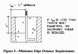
5.14.2.3 The allowable load in shear, where lbe equals or exceeds 12 bolt diameters, shall be the lesser of that given by Eq. (5-5) or Eq. (5-6).

Where lbe is less than 12 bolt diameters, the value of Bv in Equation (5-5) shall be reduced by linear interpolation to zero at an lbe distance of 1 in. (25 mm).
5.14.2.4 Combined shear and tension: Anchors in Section 5.14.2 subjected to combined shear and tension shall be designed to satisfy Eq. (5-7).


The minimum effective embedment length is illustrated in Figure 4. When anchor bolts penetrate the face shells of a masonry unit, the opening in the face shell shall be wide enough to provide at least 1 in. (25 mm) of cover around the perimeter of the bolt.

Minimum edge distance requirements are illustrated in Figure 5.


Allowable Tension and Shear
The following tables include allowable tension values for bent bar anchor bolts embedded in concrete masonry with fÆ m equal to 1500 psi and 2500 psi.
|
Table 1 Allowable Tension, lb
fÆm = 1500 psi |
||||||||
|
Bolt diameter, db, in.
|
||||||||
|
lb*
|
1/4
|
3/8
|
1/2
|
5/8
|
3/4
|
7/8
|
1
|
1 1/8
|
|
4db
6db 8db 10db |
60
130 240 360 |
130
310 550 790 |
240
540 970 1440 |
380
850 1520 2230 |
540
1230 2190 3160 |
740
1670 2980 4320 |
970
2180 3890 5680 |
1240
2770 4920 7130 |
|
* Use lesser of Ib or Ibe
|
||||||||
|
Table 2 Allowable Tension, lb
fÆm = 2500 psi |
||||||||
|
Bolt diameter, db, in.
|
||||||||
|
lb*
|
1/4
|
3/8
|
1/2
|
5/8
|
3/4
|
7/8
|
1
|
1 1/8
|
|
4db
6db 8db 10db |
80
180 310 360 |
180
400 710 790 |
310
710 1260 1440 |
490
1105 1960 2230 |
710
1590 2820 3120 |
960
2160 3850 4320 |
1260
2820 5025 5690 |
1600
3570 6350 7130 |
|
* Use lesser of Ib or Ibe
|
||||||||
|
Table 3 Allowable Shear, lb1,
2
|
||||||||
|
Bolt diameter, db, in.
|
||||||||
|
fm
|
1/4
|
3/8
|
1/2
|
5/8
|
3/4
|
7/8
|
1
|
1 1/8
|
|
1500
2000 2500 3000 3500 |
210
210 210 210 210 |
480
480 480 480 480 |
850
850 850 850 850 |
1330
1330 1330 1330 1330 |
1780
1900 1900 1900 1900 |
1920
2060 2180 2280 2370 |
2050
2200 2330 2440 2540 |
2170
2340 2470 2590 2680 |
|
1 lbe > 12db
2 fy= 36,000 psi |
||||||||
In order to keep the anchor bolts properly aligned during placement of the grout, templates are required to hold the bolts within the necessary tolerances. Templates can be either of wood or steel, depending upon the degree of accuracy required. Tolerances of 1/4 in. (6.4 mm) can be maintained using wood templates, while closer tolerances usually require the use of steel.
Locating and drilling the holes in the template after placement is recommended. To be sure that the bolts are not disturbed during the grouting operation, nuts and washers on both sides of the templates should be used to hold them securely in position.
1. BOCA National Building Code. Country Club Hills, IL: Building Officials
and Code Administrators International, Inc. (BOCA), 1993.
2. Building Code Requirements for Masonry Structures, ACI 530-95/ASCE
5-95/TMS 402-95. Reported by the Masonry Standards Joint Committee, 1995.
3. Standard Building Code. Birmingham, AL: Southern Building Code Congress
International, Inc. (SBCCI), 1994.
4. Standard Test Methods for Strength of Anchors in Concrete and Masonry
Elements, ASTM E 488-90. American Society for Testing and Materials, 1990.
5. Uniform Building Code. Whittier, CA: International Conference of Building
Officials (ICBO), 1994.