Provided by: |
| Keywords: | allowable stress design, cantilever wall, coping, earthquake, fences, footings, lateral loads, seismic loads, Seismic Performance Category (SPC), wind loads |
Concrete masonry fences and garden walls fulfill a host of functions:
Ľ privacy,
Ľ security and protection,
Ľ ornamentation,
Ľ screening from unwelcome views,
Ľ excellent sound insulation,
Ľ shade, and
Ľ wind protection.
In addition, concrete masonry provides superior durability, design flexibility and economy. The wide range of masonry colors and textures can be used to complement adjacent architectural styles or blend in with the natural landscape.
Because fences are subjected to outdoor exposure on both sides, selection of appropriate materials, proper structural design and quality workmanship are critical to maximize the durability and performance.
Fences are generally designed to ensure stability using one of five methods:
(a) as cantilever walls stabilized by continuous footings,
(b) as walls spanning between pilasters which are in turn stabilized by a footing
pad or caisson,
(c) as walls spanning between wall returns which are sufficient to stabilize
the wall,
(d) as curved walls with an arc to chord relationship that gives stability,
or
(e) as a combination of the above methods.
This TEK covers cases (a) and (d) above. Design of fences as walls spanning between pilasters (case (b)) is covered in Pier and Panel Highway Sound Barrier Wall Design (ref. 1).
Cantilever Walls
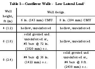
Tables 1, 2 and, 3 provide wall thickness and reinforcement requirements for cantilever walls three load cases: low wind (SPC) B. This also conforms to the Uniform Building Code (ref. 4) Seismic Zone 2 . Table 1 contains both unreinforced and reinforced design options for these conditions. For the unreinforced condition, the masonry must be bonded to the footing with mortar.
Wind and seismic loads used to develop the tables were based on Minimum Design Loads for Buildings and Other Structures, ASCE 7-93 (ref. 3). Wind pressures were based on wind exposure B, as defined by ASCE 7 (applies to urban and suburban areas or other terrain with numerous closely spaced obstructions).
Seismic Performance Categories (SPC) define the degree of protection provided against the potential hazards due to earthquakes. Both the expected level of seismicity in a geographic region and the type of structure are used to assign Seismic Performance Categories. Of the five SPCs defined by ASCE 7, labelled A through E, in order of increasing degree of protection from earthquakes, only the first four (SPC A-D) apply to fences.
Design Parameters for Fence Tables
Tables 1, 2 and, 3 are based on the following:
1. Running bond masonry.
2. ASTM C 90 concrete masonry units and: a. For unreinforced masonry - Type
N, S, or M portland cement and lime mortar or Type S or M masonry cement mortar.
b. For reinforced masonry - Type N, S, or M either portland cement and lime
or masonry cement mortar achieving an f'm of 1350 psi with the following
exceptions: (1). Masonry cements may not be used in SPC D and Seismic Zones
2, 3, and 4. (2). Type N mortar may not be used in SPC D and Seismic Zones 3
and 4.
3. Grade 60 reinforcing steel.
4. Working Stress Design per Building Code Requirements for Masonry Structures
(ref. 2) including a permitted 1/3 increase in allowable stresses for wind or
seismic.
5. The weight of masonry walls was considered in offsetting the bending moment
produced by the lateral loads based on a density of masonry of 125 pcf (2002
kg/m3).
|
|
|
|
Low Lateral Loads
The low lateral load case presented in Table 1 is based on the higher of loads generated by a 70 mph (113 km/hr) fastest mile wind speed Exposure B or Seismic Performance Category (SPC) B. This also conforms to the Uniform Building Code (ref. 4) Seismic Zone 2 . Table 1 contains both unreinforced and reinforced design options for these conditions. For the unreinforced condition, the masonry must be bonded to the footing with mortar.
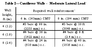
Moderate Lateral Loads
The moderate lateral load case presented in Table 2 is based on a basic wind speed of 90 mph (145 km/hr) fastest mile, exposure category B, and a Seismic Performance Category (SPC) C or Uniform Building Code (ref. 4) Seismic Zone 2. However, there is a difference between the last two regarding minimum reinforcement for seismic. ASCE 7 requires minimum reinforcement in either the vertical or horizontal direction for SPC C whereas the Uniform Building Code (ref. 4) requires a minimum amount in both directions. See Footnote 2 of Table 2 for these requirements on fences.
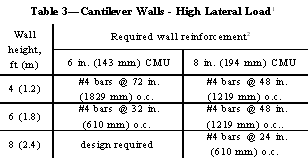
High Lateral Loads
The high lateral load case, Table 3, is based on a basic wind speed of 110 mph (177 km/hr) fastest mile, exposure category B, and a Seismic Performance Category (SPC) D. This is similar to Seismic Zones 3 and 4 in the Uniform Building Code (ref. 4).
Minimum reinforcement is required in both the vertical and horizontal directions for SPC D as indicated in Footnote 2 of Table 3.
In cantilever walls, the footing holds the wall in position and resists overturning and sliding due to lateral loads. Dowels typically extend up from the footing into the wall to transfer stresses and anchor the wall in place. Dowels should be at least equal in size and spacing to the vertical fence reinforcement. Minimum lap splicing with the vertical wall reinforcement should be 48 bar diameters. This amounts to 18 in. (457 mm) for #3 bars and 24 in. (610 mm) for #4 bars. Footings over 24 in. (610 mm) wide require transverse reinforcement. In footings 24 in. (610 mm) wide and less that do not have transverse reinforcement, the hook of the dowel bar should extend to within 3 in. (76 mm) of the toe of the footing. (See Figure 1). In all cases the hook should be at the bottom of the footing (3 in. (76 mm) clearance to the subgrade) in order to develop the strength of the bar at the top of the footing.
The design of the concrete footings conforms to American Concrete Institute requirements as set forth in Building Code Requirements for Reinforced Concrete, ACI 318 (ref. 5).
Serpentine Walls
The use of serpentine garden walls or ôfolded plateö wall designs adds interesting and pleasing shapes to enhance the landscape. The returns or bends in these walls also provide additional lateral stability, which allows the walls to be built higher than if they were straight.
Serpentine and folded plate walls are designed using empirical design guidelines that historically have proven successful over many years of experience. The guidelines presented here are based on lateral loads up to 20 psf (958 Pa), with no reinforcement.
Design guidelines are illustrated in Figure 2, and include:
Ľ wall radius should not exceed twice the height,
Ľ wall height should not exceed twice the width (or the depth of curvature -
see Figure 2),
Ľ wall height should not exceed fifteen times the wall thickness, and
Ľ the free end(s) of the serpentine wall should have additional support such
as a pilaster or a short-radius return.
A wooden template, cut to the specified radius, is helpful for periodically
checking the curves for smoothness and uniformity.

Materials
All materials (units, mortar, grout and reinforcement) should comply with applicable ASTM standards. Additional material requirements are listed under the section "Design Parameters for Fence Tables" on page 2 of this document. To control shrinkage cracking, it is recommended that horizontal joint reinforcement at 16 in. (406 mm) on center be utilized and that control joints be placed in accordance with local practice. In addition, a bond beam in the top course is recommended to help structurally tie the wall together.
Copings
Copings provide protection from water penetration and are also often used to enhance the wall's appearance. Various materials such as concrete brick, cast stone, brick and natural stone are suitable for coping concrete masonry fences.
Copings should project at least 1/2 in. (13 mm) beyond the face of the wall on both sides to provide a drip edge, which will help keep water off the face of the wall. A bond beam in the top course, or fully grouting the top course, also helps prevent water entry.
1. Pier and Panel Highway Sound Barrier Wall Design, NCMA TEK 14-15A. National Concrete Masonry Association, 1997.
2. Building Code Requirements for Masonry Structures, ACI 530-95/ASCE 5-95/TMS 402-95. Reported by the Masonry Standards Joint Committee, 1995.
3. Minimum Design Loads for Buildings and Other Structures, ASCE 7-93. American Society of Civil Engineers, 1993.
4. Uniform Building Code. Chapters 16 and 21. Whittier, CA: International Conference of Building Officials (ICBO), 1997.
5. Building Code Requirements for Reinforced Concrete, ACI 318-95. Detroit, MI: American Concrete Institute, 1995.