Provided by: |
| Keywords: | condensation, moisture, thermal bridging, thermal insulation, thermal properties |
Concrete brick offers a wide variety of choices of natural faces and finishes for walls. Variations in texture, color, and size, along with choices in bonding patterns and joint treatment, make concrete brick an excellent choice for exterior and interior walls in residential, commercial and public buildings. In addition, concrete brick can be used in both structural and veneer applications and is economical, durable, easy to maintain, fire resistant, and reduces sound transmission. Concrete brick are used both in composite wall construction and as a nonload-bearing veneer in cavity wall construction. Composite walls are multiwythe walls where the wythes of masonry are connected such that stresses are transferred between the wythes, allowing the wythes to act as a single member in resisting loads. Typically, masonry cavity walls do not allow composite action between wythes, requiring instead that each wythe individually resist the loads imposed on it.
Causes
A thermal bridge allows heat to "short circuit" insulation. Typically, this occurs when a material of high thermal conductivity, such as nails, steel framing, or concrete, penetrates or interrupts a layer of low thermal conductivity material, such as insulation. Thermal bridges can also occur where building elements are joined, such as exposed concrete floor slabs and beams that abut or penetrate the exterior walls of a building.
Thermal bridging can be caused by improper installation of materials. For example, gaps in insulation can allow heat to escape around the insulation. For this reason, insulation should be installed without gaps at the floor, ceiling, or between sheets or batts, and should be installed so that it stays in position over time.
Thermal bridging is primarily associated with conduction heat transfer, where heat flows through solid materials from warmer to colder areas. However, thermal bridging effects can be magnified by heat and moisture transfer due to air movement, particularly when warm, moist air enters the wall. For this reason, buildings with typically high interior humidity levels, such as swimming pools, spas, and cold storage facilities, are particularly susceptible to moisture damage. Proper installation of vapor and air retarders can greatly reduce moisture damage caused by thermal bridges.
Minimizing moisture leakage will also alleviate thermal bridging due to air leakage for two reasons: air will flow through the same points that allow moisture entry; and water leakage can lead, in some cases, to degradation of air barriers and insulation materials. Recommendations for proper design and construction to minimize water entry are covered in other NCMA TEKs.

Effects
Possible effects of thermal bridges are:
� increased heat loss through the wall, leading to higher operating costs
� local cold spots on the interior at the thermal bridge locations, leading to occupant discomfort and, in some cases, to condensation on the interior wall surface
� local cold spots within the wall construction, leading to moisture condensation within the wall, and possibly to damage of the building materials
Not all thermal bridges cause these severe effects. However, the severity of a particular thermal bridge should be judged by the effect of the thermal bridge on the overall energy performance of the building; the effect on occupant comfort; the impact on moisture condensation and associated aesthetic and/or structural damage; and degradation of the building materials. Appropriate corrective measures can then be applied to the design.
In a single wythe concrete masonry wall, the webs of the block can act as thermal bridges, particularly when the cores of the concrete masonry units are insulated. This thermal bridging is accounted for when calculating the R-value of the block wall, so that additional heat loss and gain due to thermal bridging can be accurately predicted during design (see TEK 6-1A for further information on calculating R-values of concrete masonry walls).
The heat loss through the webs is rarely severe enough to cause moisture condensation on the block surface, or other aesthetic or structural damage. In severe climates or certain interior environments where condensation may occur under some conditions, the thermal bridging effects can be eliminated by applying insulation on the exterior or interior of the block, rather than in the cores. Under these conditions, a vapor retarder should typically be placed directly behind the interior finish. In addition, thermal bridging through webs can be reduced by using a lighter weight masonry unit, or by using special units with reduced web size, or by using units that have fewer cross webs.
Horizontal joint reinforcement is often used to control shrinkage cracking in concrete masonry. Calculations have shown that the effect of the joint reinforcement on the overall heat transfer coefficient of the masonry wall is on the order of one to three percent, which has a negligible impact on the energy use of the building.
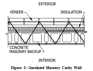
Typically, insulation is placed in the cavity of multi-wythe walls, as shown in Figure 2. The insulation used must not impede water drainage in the cavity, and must not degrade in the presence of moisture.
Because the ties are isolated from the interior, the interior surface of the wall will remain at temperatures close to the interior temperature. The interior finish material is not likely to be damaged due to moisture condensation, and occupant comfort is not likely to be affected. As with horizontal joint reinforcement in single wythe construction, the type, size, and spacing of the ties will affect the impact on energy use.
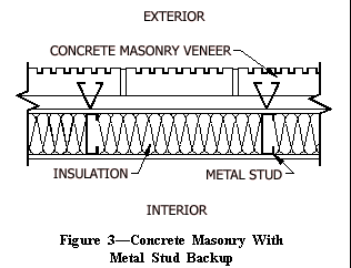
Figure 3 shows a cross section of a typical concrete masonry veneer over a metal stud backup. Metal studs act as strong thermal bridges in an insulated wall system. Almost 1,000 times more heat flows through the steel than through mineral fiber insulation of the same thickness and area. The steel stud allows heat to bypass the insulation, and greatly reduces the insulation's effectiveness.

| Table 1�R-Value Correction Factors for Insulated Metal Stud Walls (ref. 1) | |||||
| Size of stud | Gauge of metal stud | Spacing of framing, in. | Cavity insulation R-value, hrft20F/Btu | Correction factor | Effective framing/cavity R-value, hrft20F/Btu |
| 2X4 | 18-16 | 16 | 11 | 0.50 | 5.5 |
| 13 | 0.46 | 6.0 | |||
| 15 | 0.43 | 6.4 | |||
| 2X4 | 18-16 | 24 | 11 | 0.60 | 6.6 |
| 14 | 0.55 | 7.2 | |||
| 15 | 0.52 | 7.8 | |||
| 2X6 | 18-16 | 16 | 19 | 0.37 | 7.1 |
| 21 | 0.35 | 7.4 | |||
| 2X6 | 18-16 | 24 | 19 | 0.45 | 8.6 |
| 21 | 0.43 | 9.0 | |||
| 2X8 | 18-16 | 16 | 25 | 0.31 | 7.8 |
| 2X8 | 18-16 | 24 | 25 | 0.38 | 9.6 |
The American Society of Heating, Refrigerating and Air-Conditioning Engineers (ASHRAE) has published correction factors (ref. 1) to account for the effect of thermal bridging. Table 1 shows that thermal bridging through metal studs effectively reduces the R-value of the wall by 40 to 69 percent, depending on the size and spacing of the metal studs, and on the R-value of the insulation. The effective framing/cavity R-value shown in Table 1 is the R-value of the insulated metal stud section, accounting for thermal bridging. Using these corrected R-values allows the designer to adequately account for the increased energy use due to the thermal bridging.
Because the metal studs are typically in contact with the interior finish, local cold spots can develop at the stud locations. In some cases, moisture condenses, causing dampness along these strips. The damp areas tend to retain dirt and dust, causing darker vertical lines on the interior at the metal stud locations.
If warm, moist indoor air penetrates into the wall, moisture is likely to condense on the outer flanges of the metal studs, increasing the potential for corrosion of studs and connectors and structural damage of the wall. Gypsum sheathing on the exterior of the studs can also be damaged due to moisture, particularly during freeze-thaw cycles.


Another common thermal bridge that can occur in exterior walls is shown in Figure 4. When this wall system is insulated on the interior, as shown on the left, thermal bridging occurs at the steel beam and where the slab penetrates the interior masonry wythe.
A better alternative in this case is to place insulation in the cavity, as shown on the right in Figure 4, rather than on the interior. This insulation strategy effectively isolates both the slab edge and the steel beam from the exterior, substantially reducing heat flow through these areas. Studies have shown that insulating in the cavity in this case can eliminate the condensation potential and significantly decrease heating loads (ref. 2). A third alternative, not illustrated, is to install insulation on the interior of the steel beam. This solution, however, does not address the thermal loss through the slab edge. In addition, the interior insulation causes the temperature of the steel beam to be lower, and can lead to condensation unless a tight and continuous vapor retarder is provided.
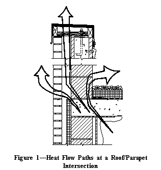
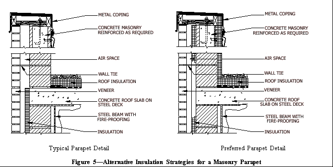
Because a parapet is exposed to the outside environment on both sides, it can act as a thermal fin, wicking heat up through the wall. Figure 5 shows two alternative insulation strategies for a masonry parapet. On the left, even though the slab edge is insulated, reducing heat loss through the wall, the parapet is uninsulated. This allows heat loss between the roof slab and the masonry backup wythe.
A better alternative is shown on the right in Figure 5. Here, the parapet itself is insulated, maintaining a thermal boundary between the interior of the building and the outdoor environment. This significantly reduces heating and cooling loads, and virtually eliminates the potential for condensation on the underside of the roof slab.

1. Addenda to Energy Efficient Design of New Buildings Except Low-Rise Residential Buildings, ASHRAE/IES 90.1g. American Society of Heating, Refrigerating, and Air-Conditioning Engineers, 1993.
2. Catalog of Thermal Bridges in Commercial and Multi-Family Residential Construction. Steven Winter Associates, Inc., ORNL/Sub/88-SA407/1, Oak Ridge National Laboratory, Oak Ridge, TN, 1989.
3. Tuluca, Adrian. Thermal Bridges in Buildings. Progressive Architecture, December 1992.
4. Persily, Andrew K. Envelope Design Guidelines for Federal Office Buildings: Thermal Integrity and Airtightness, NISTIR 4821. U. S. National Institute of Standards and Technology, 1993.
5. R-Values of Multi-Wythe Concrete Masonry Walls, TEK 6-1A. National Concrete Masonry Association, 1995.