| Value of Av | I | II | III |
| Av < 0.05 0.05 0.10 0.15 0.20 |
A B C C |
A B C D D |
A |
Provided by: |
| Keywords: | allowable stress design, empirical design, reinforced concrete masonry, seismic, veneers |
Building Code Requirements for Masonry Structures, ACI 530/ASCE 5/TMS 402 (ref. 2), Chapter 10, contains seismic design provisions intended to improve the performance of masonry structures in earthquakes. The provisions are categorized according to the Seismic Performance Categories defined in Minimum Design Loads for Buildings and Other Structures, ASCE 7 (ref. 6) and are based on the NEHRP Recommended Provisions for the Development of Seismic Regulations for New Buildings (ref. 1). These provisions apply to all masonry structures with the exception of glass unit masonry and masonry veneer.
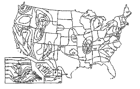
Seismic Performance Categories (SPC) define the degree of protection provided to the public against the potential hazards due to earthquakes. Both the expected level of seismicity in a geographic area and the type of building are used to assign Seismic Performance Categories. The expected level of seismicity is determined based on the effective peak velocity-related acceleration map in ASCE 7 (see Figure 1). The coefficients in the map are a measure of the effect of design ground motion on lateral load.
 |
|||||
| Figure 1 SeismicPerformance Categories and Accelerations | |||||
| Seismic Performance Category | |||||
| Seismic Hazard Exposure Group | |||||
|
|||||
|
|||||
Buildings are classified into Seismic Hazard Exposure Groups as follows:
Group III: buildings having essential facilities that are required for post-earthquake
recovery, such as fire, rescue and police stations, hospitals, etc.
Group II: buildings having a substantial public hazard due to occupancy or use,
such as schools and assembly buildings.
Group I: buildings not assigned to Groups II or III.
Figure 1 includes the correlation between the effective peak velocity-related acceleration, Av, the building Seismic Hazard Exposure Group, and the Seismic Performance Category.
ASCE 7 defines five SPCs, labelled as A through E, in order of increasing degree of protection from earthquakes. Thus, buildings designated as SPC A require few additional design requirements, while construction designated as SPC E is required to meet the strictest seismic design provisions in order to minimize risk of failure during an earthquake.
The design provisions described below apply to the design of masonry building elements, with the exception of glass unit masonry and veneers. Seismic design provisions for veneers are provided at the end of this section.
The requirements listed below for the various Seismic Performance Categories are cumulative. That is, masonry in buildings assigned to Seismic Performance Category B must meet the requirements for SPC A as well as those for B. Buildings assigned to SPC C must meet the requirements for Categories A, B, and C, etc.
General
Designers have the option of using several design methods for masonry structures: empirical design; allowable stress design (either unreinforced or reinforced); or a pseudo-strength design procedure included in Chapter 10 of the Code. There are, however, restrictions placed on the use of the empirical design method and on the use of unreinforced masonry. Table 1 summarizes which design procedures may be used for the various Seismic Performance Categories.
Empirical design uses a rule-of-thumb type approach to sizing masonry elements which is based on successful performance in lieu of an engineering analysis. Empirical design provisions are contained in Chapter 9 of the Code (see also ref. 5).
Allowable stress design is an analytical approach where members are designed to ensure that calculated stresses in compression, flexure, and shear are below the code-required allowable stresses. Allowable stress design provisions are contained in Chapters 6 and 7 of the Code (see ref. 3 for a summary of the provisions).
| Table 1 - Permitted Design Procedures for each Seismic Performance Category | ||||
| Design methods | ||||
| SPC | Empirical design | Allowable stress design unreinforced | Allowable stress design reinforced | "Psuedo-strength" design |
| A B C D E |
T Ta Ta |
T Tb Tb |
T T T T T |
T T T T T |
a The lateral force-resisting system of buildings cannot be designed using empirical design in SPC B and C.
b Although the designer has the option of designing unreinforced walls in SPC B and C, the design shear values are considerably less for reinforced masonry than for unreinforced. In this way, the use of a more ductile system is encouraged. References 4 and 6 contain a more complete discussion on response modification factors and seismic base shear equations.
The pseudo-strength design method in Chapter 10 of the Code is based on the alternate design provisions of the NEHRP criteria (ref. 1). This pseudo-strength design method modifies allowable stress values to approximate strength value levels. The design strength of the masonry member must be equal to or greater than the required strength.
The required strength is determined using the loads and load combinations of ASCE 7. The design strength is equal to the nominal strength multiplied by a strength reduction factor, f, to achieve a reliable design level value. The nominal capacity of members and connections is based on allowable stress values increased by a factor of 2.5 and further increased by 1/3 (for load combinations including wind or seismic). The strength reduction factor accounts for variations in material properties and construction. Strength reduction factors are listed in Table 2 for use with this approach.
In addition, the calculated story drift of masonry structures due to the combination of seismic forces and gravity loads is limited to 0.007 times the story height.
| Table 2 - Strength Reduction Factors, f, for Use With Pseudo-Strength Design Procedures of Chapter 10 | |
| Type of load Axial load and flexure except for flexural tension in unreinforced masonry Flexural tension in unreinforced masonry Shear Shear and tension on anchor bolts embedded in masonry |
f 0.8 0.4 0.6 0.6 |
Seismic Performance Categories A and B
In areas of low seismic risk, the existing design provisions of the Code provide for adequate performance of masonry. The one additional requirement is that masonry walls are required to be anchored to the roof and all floors providing lateral support for the wall. The connections must be capable of resisting the greater of: a seismic lateral force induced by the wall; or 1000 times the effective peak velocity-related acceleration, as listed in Figure 1.
As noted in Table 1, empirical design may not be used to design the lateral force resisting system of buildings assigned to Seismic Performance Category B.
Seismic Performance Category C
In addition to the requirements above for SPC A and B, structures assigned to SPC C must meet additional minimum levels of reinforcement and detailing. These requirements must be met regardless of the method used to design the structure.
Masonry partition walls, screen walls, and other masonry elements that are not part of the lateral force-resisting system must be analyzed to determine their effect on the response of the system. They must be capable of carrying any applicable vertical loads, as well as the induced moment due to the design story drift. These elements must be isolated from the structure so that vertical and lateral forces are not imparted to these elements. Isolation joints and connectors between these elements and the structure shall be designed to accommodate the design story drift.
Elements that are not part of the lateral force resisting system must comply with a minimum level of reinforcement requirements in either the horizontal or vertical direction as shown in Figure 2.
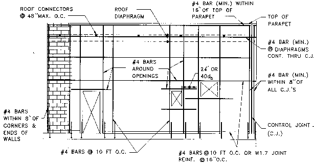
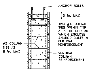
Prescriptive minimum reinforcement requirements for elements that are part of the lateral force-resisting system are shown in Figures 3 and 4. For these elements, connectors must be provided to transfer forces between masonry walls and horizontal elements. The connectors must be designed to resist the greater of the seismic lateral force, or a horizontal force of 200 lb/ft (2919 N/m) acting either perpendicular or parallel to the wall. The maximum spacing between connectors is 4 ft (1.2 m). When anchorage is between masonry walls and wood framed floors or roofs, the designer should avoid the use of wood ledgers in cross-grain bending.
| Figure 2Minimum Reinforcement for Elements Which are Not Part of the Lateral Force-Resisting System of Buildings assigned to SPC C |
 |
| * Horizontal joint reinforcement must consist of at least 1 longitudinal W1.7 wire for walls not exceeding 4 in. (102 mm) in thickness and at least 2 longitudinal W1.7 wires for walls greater than 4 in. (102 mm) in thickness. |
| Figure 3 - Minimum Shear Wall Reinforcement for SPC C |
 |
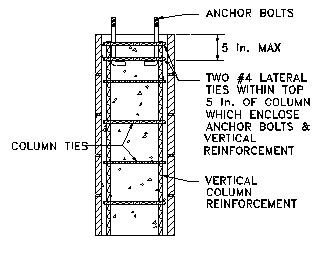
| Figure 4 - Tie Requirements Around Anchor Bolts in Columns for SPC C |
 |
Seismic Performance Category D
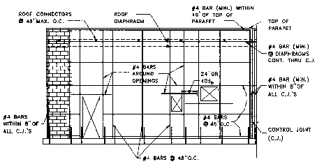
Additional prescriptive reinforcement requirements apply in SPC D, as illustrated in Figures 5 and 6. The minimum areas of both the horizontal and vertical reinforcement must also be at least 0.007 times the gross cross-sectional area of the wall, and the sum of the horizontal and vertical reinforcement areas must be at least 0.02 times the gross-cross-sectional area of the wall (see Table 3). These reinforcement requirements are based on historical requirements in areas of high seismic loading. Since the minimum required reinforcement may also be used to satisfy design requirements, at least 1/3 of the minimum amount is reserved for the lesser stressed direction in order to ensure an appropriate distribution in both directions. Additional requirements may also apply to masonry constructed in a stack bond pattern (see Addendum to Chapter 10)
For shear walls, the maximum spacing of reinforcement is taken as the smallest of: 1/3 the length of the shear wall; 1/3 the height of the shear wall; or 48 in. (1219 mm). The minimum cross-sectional area of vertical reinforcement is 1/3 of the required shear reinforcement. The shear reinforcement must be anchored around vertical reinforcing bars with a standard hook.
Standard hooks for lateral tie anchorage must be either a 135o or 180o standard hook.
In addition, neither Type N mortar nor masonry cement mortar may be used as part of the lateral force-resisting system of structures assigned to SPC D.
| Figure 5Minimum Reinforcement for Walls of Buildings assigned to SPC D and E |
 |
| Figure 6 - Minimum Column Reinforcement for SPCs D and E |
 |
| Table 3Minimum Distributed Wall Reinforcement for Buildings assigned to SPC D | |||
| Nominal Wall Thickness, in. (mm) | Minimum Sum of the Vertical and Horizontal Reinforcement Areasa in.2/ft (mm2/m) | Minimum Reinforcement Are as in both Horizontal and Vertical Directionsb in.2/ft (mm2/m) | Minimum Bar Size for distributed reinforcement spaced at 48 in. (1.22m) oc. |
|
6 (152) |
0.135 (286) |
0.047 (100) |
#4 |
|
8 (203) |
0.183 (383) |
0.064 (137) |
#5 |
|
10 (254) |
0.231 (489) |
0.081 (171) |
#6 |
|
12 (305) |
0.279 (590) |
0.098 (207) |
#6 |
| a Based on the minimum
reinforcing ratio of 0.002 times the gross cross-sectional area of the wall
b Based on the minimum reinforcing ratio each direction of 0.0007 times the gross cross-sectional area of the wall |
|||
Seismic Performance Category E
In addition to the previous requirements for SPC A through D, there are additional requirements for stack bond masonry in SPC E. Stack bond masonry must be solidly grouted and constructed of either hollow open-end units or two wythes of solid units
When stack bond masonry is not part of the lateral force-resisting system, horizontal reinforcement with a cross-sectional area of at least 0.0015 times the gross cross-sectional area of the wall must be provided at a spacing of no more than 24 in. (610 mm).
When stack bond masonry is part of the lateral force-resisting system, the area of horizontal reinforcement must equal or exceed 0.0025 times the gross cross-sectional area of masonry, with a maximum spacing of horizontal reinforcement of 16 in. (406 mm).
Addendum to Chapter 10 of the Code
The provisions at the end of Code Section 10.6.3 imply that the maximum spacing of reinforcement is 24 in. (610 mm) instead of 48 in. (1219 mm) when walls are not solid grouted and are not constructed with either open-end units, full head joints or two wythes of solid masonry. These provisions were intended to apply to stack bond masonry and an addendum will change the last sentence of Section 10.6.3 to:
...The maximum spacing of reinforcement shall be 48 in. (1219 mm) except for stack bond masonry. Wythes of stack bond masonry shall be constructed of fully grouted hollow open -end units, fully grouted hollow units laid with full head joints, or solid units. Maximum spacing of reinforcement for walls with stack bond masonry shall be 24 in. (610 mm).
Section 12.12 of the Code includes additional requirements for masonry veneer anchored to structures assigned to Seismic Performance Categories C, D, and E. Like the requirements for walls, these requirements are cumulative.
Anchored veneer on buildings assigned to SPC C must is required to be isolated from the structure at the sides and top so that vertical and lateral seismic forces resisted by the structure are not imparted to the veneer wythe. This isolation reduces accidental loading and permits larger building deflections to occur without damaging the veneer.
The weight of the anchored veneer for each story of buildings assigned to SPC D must be supported independently of other stories to reduce the size of potentially damaged areas. Additionally, the maximum wall area supported by each anchor must be reduced by 75% for veneer on buildings assigned to SPC D. The maximum horizontal and vertical spacings are however unchanged. The reduction in allowable supported area increases the number of anchors that are provided which in turn increases the veneer stability, reducing the possibility of falling debris. Anchored veneer for buildings assigned to SPC D must also have continuous single-wire joint reinforcement of minimum wire size W1.7 at a maximum spacing of 18 in. (450 mm) on center vertically. The continuous wires are required to provide ductility and post-cracking strength.
In addition to the above, anchored veneer for buildings assigned to SPC E must also have vertical expansion joints at all returns and corners as further protection for the veneer against building deflections. Anchors must be mechanically attached to the joint reinforcement required above with clips or hooks.
1. 1992 NEHRP Recommended Provisions for the Development of Seismic Regulations for New Buildings. Building Seismic Safety Council, 1992.
2. Building Code Requirements for Masonry Structures, ACI 530-95/ASCE 5-95/TMS 402-95. Reported by the Masonry Standards Joint Committee, 1995.
3. Building Code Requirements for Masonry Structures, NCMA TEK 1-3A. National Concrete Masonry Association, 1996.
4. Concrete Masonry Design for Seismic Forces, NCMA TEK 14-12. National Concrete Masonry Association, 1989.
5. Empirical Design of Concrete Masonry Walls, NCMA TEK 14-8. National Concrete Masonry Association, 1993.
6. Minimum Design Loads for Buildings and Other Structures, ASCE 7-93. American Society of Civil Engineers, 1993.