Provided by:
|
| Keywords: | anchorage, cavity walls, joint reinforcement, multi-wythe walls, veneer, wall ties |
In addition to use structurally as through-the-wall units, or as the exterior wythe of composite and cavity walls, concrete brick and architectural facing units are also used as veneer over various backing surfaces. The variety of surface textures, colors, and patterns available makes concrete masonry a versatile and popular exterior facing material. Architectural units such as split-face, scored, fluted, ground face, and slump are available in a variety of colors and sizes to complement virtually any architectural style.
Veneer-GeneralVeneer is nonstructural facing of brick, tile, concrete masonry, or other material securely attached to a wall or backing. Veneers provide the exterior wall finish and transfer out-of-plane loads directly to the backing, but they are not considered to add to the load-resisting capacity of the wall system. Backing material may be masonry, concrete, wood studs or metal studs.
The height and length of the veneered area is typically not limited by the codes. The exception is when veneer is applied over wood stud construction, where veneer is typically limited to a height of 30 ft (9.1 m) above the foundation unless approved by the building official.
For the purposes of design, veneer is assumed to support no load other than its own weight plus the vertical dead load of the veneer above. The backing must be designed to support the vertical and lateral loads imposed by the veneer in addition to the design loads on the wall since it is assumed the veneer does not add to the strength of the wall.
Masonry veneers may be designed using engineered design methods to proportion the stiffness properties of the veneer and the backing to limit stresses in the veneer and achieve compatibility (ref. 6). As an alternative, prescriptive code requirements have been developed based on judgement and successful performance. The prescriptive requirements relate to size and spacing of anchors and methods of attachment.
In addition to structural requirements, differential movement between the veneer and its supports must be accommodated. Movement may be caused by temperature changes, moisture-volume changes, or deflection. In concrete masonry, control joints and horizontal joint reinforcement effectively relieve stresses and accommodate small movements. Control joints should be placed in the veneer at the same locations as those in the backing, or as required to prevent excessive cracking.
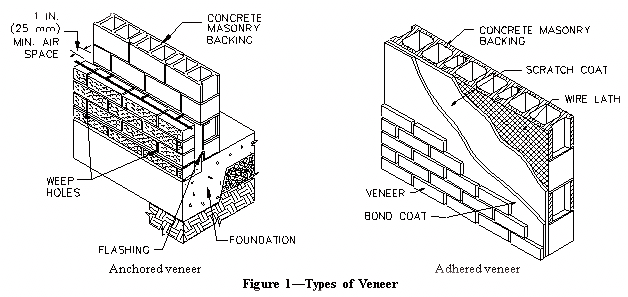
Two types of veneer are discussedŚanchored veneer and adhered veneer, illustrated in Figure 1. They are differentiated by the method used to attach the veneer to the backing.

Anchored veneer is veneer which is supported laterally by the backing and supported vertically by the foundation or other structural elements. Anchors are used to secure the veneer and to transfer loads to the backing. Anchors and supports must be noncombustible and corrosion-resistant. In areas where seismic activity is a factor, anchored veneer and its attachments must meet additional requirements to assure adequate performance in the event of an earthquake.
Some codes require units used for anchored veneer to be at least 1 5/8 in. (41 mm) thick if the veneer units are solid, and at least 2 5/8 in. (67 mm) thick for hollow units (refs. 1,5).
Where anchored veneers are not self-supporting, such as over openings, the veneer must be supported by noncombustible lintels or supports. Codes may limit deflection of these horizontal supports to 1/600 of the span or 0.3 in. (8 mm), whichever is smaller (refs. 1, 5, 7).
Flashing and weep holes or vents should be provided in the veneer to divert water to the exterior. Weep holes should be at least 3/16 in. (5 mm) in diameter and spaced not more than 32 in. (812 mm) on center. Weep holes may be formed from partially or fully open head joints, or by inserting plastic tubes or wicks in the mortar joints, although open weep holes allow more complete drainage than wicks. Open weep holes can also serve as vents, allowing air circulation in the cavity to speed the rate of drying. Additional vents may be installed at the tops of walls to further increase air circulation. The backing must be designed and detailed to resist water penetration. More detailed information is contained in Use of Flashing in Concrete Masonry Walls and Concrete Masonry Cavity Wall Details (refs. 8, 3).
For anchored veneer, codes typically require a 1 in. (25 mm) minimum air space be maintained between the veneer and backing to facilitate drainage (refs. 1, 2, 5, 7). As an alternative, the Uniform Building Code (ref. 7) allows mortar to be slushed into this space. Except as noted below, the maximum distance between the inside face of the veneer and the outside face of the backing is limited to 4 1/2 in. (110 mm).
Anchors
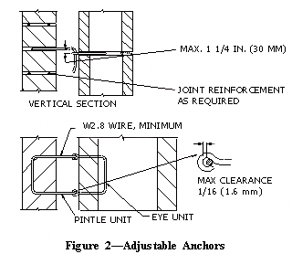
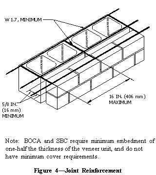
Veneers may generally be anchored to the backing using corrugated sheet metal anchors, sheet metal anchors, wire anchors, joint reinforcement, or adjustable anchors, although building codes may contain restrictions on the use of some anchors. Model building codes contain requirements for each anchor type. These requirements are summarized in Figures 2 through 4.
 |
 |
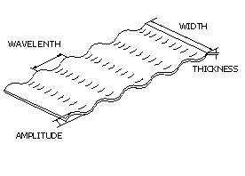 |
Size requirements: | ||||
| Code |
Min. width,
in. (mm) |
Min. thickness,
in. (mm) |
Wavelength,
in. (mm) |
Amplitude,
in. (mm) |
|
| MSJC (ref. 2)åå |
7/8 (22)
|
0.03 (0.76)
|
0.3-0.5 (7.5-12.5)
|
0.06-0.10 (1.5-2.5)
|
|
| BOCA (ref. 1)å |
7/8 (22)
|
0.029 (0.74)
|
(no req'mt)
|
(no req'mt)
|
|
| SBC (ref. 5)å |
7/8 (22)
|
0.029 (0.74)
|
(no req'mt)
|
(no req'mt)
|
|
| UBC (ref. 7) |
3/4 (19)
|
0.03 (0.76)
|
(no req'mt)
|
(no req'mt)
|
|
| å Requires minimum embedment into veneer of
half the veneer thickness. åå Requires 1.5 in. (38 mm) minimum embedment and 0.625 in. (16 mm) minimum cover from exterior. |
|||||
|
Figure 3ŚCorrugated Sheet Metal Anchors
|
|||||
Attachment to Backing
When masonry veneer is anchored to wood backing, each anchor is attached to the backing with a corrosion-resistant 8d common nail, or a fastener with equivalent or greater pullout strength. For proper fastening of corrugated sheet metal anchors, the nail or fastener must be located within 1/2 in. (13 mm) of the 90░ bend in the anchor. The maximum distance between the inside face of the veneer and outside face of the solid sheathing is 1 in. (25 mm) when corrugated anchors are used. For other anchors, the 41/2 in. (110 mm) maximum distance applies. Codes also require sheathing on both sides of the studs. The exterior sheathing must be either water repellent or be protected with a water repellent membrane to protect the backing from any water which may penetrate the veneer. Stud spacing is limited to either 24 in. (610 mm) on center (refs. 1, 5) or 16 in. (406 mm) on center (ref. 7).
When masonry veneer is anchored to steel backing, adjustable anchors must be used to attach the veneer. Each anchor is attached with corrosion-resistant screws that have a minimum nominal shank diameter of 0.19 in. (4.8 mm). Cold-formed steel framing must be corrosion resistant and should have a minimum base metal thickness of 0.043 in. (1.1 mm) (ref. 2). Sheathing and stud spacing requirements are similar to those for wood stud backing.
Masonry veneer anchored to masonry backing may be attached using wire anchors, adjustable anchors, or joint reinforcement. Veneer anchored to a concrete backing must be attached with adjustable anchors.
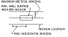 Table 1-Anchor Spacing Requirementså
 |
||||||
|
||||||
| Code | Backing | Type of Anchor | Max wall surface area, ft▓ (m▓) | Max. vertical spacing in. (mm) | Max horizontal spacing in. (mm) | |
| MSJC (ref. 2) | masonry | wire, adjustable, or joint replacement | 2.67 (0.25) | 18 (457) | 32 (813) | |
| concrete | adjustable | 2.67 (0.25) | 18 (457) | 32 (813) | ||
| wood stud | adjustable two-piece, anchors of wire size
W 1.7, or 22 gauge corrugated sheet metal all other anchors |
2.67 (0.25) 3.5 (0.33) |
18 (457) 18 (457) |
32 (813) 32 (813) |
||
| metal stud | adjustable | 2.67 (0.25) | 18 (457) | 32 (813) | ||
| BOCA (ref. 1) | masonry or concrete | wire ties or joint reinforcement | 3 (0.28) | 16 (406) | 32 (813) | |
| wood stud | corrugated sheet metal or wire ties | 3 (0.28) | 16 (406) | 32 (813) | ||
| metal stud | wire ties | 2.67 (0.25) | 16 (406) | 24 (610) | ||
| SBC (ref. 5) | masonry or concrete | corrugated sheet metal, wire ties, or joint reinforcement | 3 (0.28) | 16 (406) | 32 (813) | |
| wood stud | corrugated sheet metal or wire tires | 3 (0.28) | 16 (406) | 32 (813) | ||
| metal stud | wire ties | 3 (0.28) | 16 (406) | 32 (813) | ||
| UBC (ref. 7) | any | sheet metal, wire ties, or joint reinforcement | 2 (0.19) | (no requirement) | 24 (610) | |
| åCodes may require additional anchors adjacent to openings, or when vaneer is laid in other than running bond. | ||||||
Adhered veneer is veneer secured and supported through adhesion to a bonding material applied over the backing. Masonry units used in this application must be less than 15/8 in. (41 mm) thick and weigh not more than 15 lb/ft2 (refs. 1, 5, 7). Adhered veneer and its backing must also be designed to have sufficient bond to withstand a shearing stress of 50 psi (345 kPa) after curing 28 days (refs. 1, 5).
Backing materials for adhered veneer must be continuous (wood frame backing with adhered veneer must be backed with a solid water repellent sheathing). The surface of the backing material must be capable of securing and supporting the imposed loads of the veneer. Materials that may affect bond, such as dirt, grease, oil, or paint (except portland cement paint) should be cleaned off the backing surface prior to adhering the veneer.
Two methods of application are permitted:
Method 1: A paste of neat portland cement is brushed on the backing and the on back of the veneer unit immediately prior to applying the mortar coat. This cement coating provides a good bonding surface for the mortar. Type S mortar is then applied to the backing and to each veneer unit in a layer approximately 3/8 in. (9.5 mm) thick. Sufficient mortar should be used so that a slight excess is forced out the edges of the units. The units are then tapped into place to eliminate voids between the units and the backing which could reduce bond. The resulting thickness of mortar between the backing and veneer must be between 1/2 and 1 1/4 in. (13 and 32 mm).
Method 2: Units not over 1 in. (25 mm) thick are restricted to an area of 81 in.▓(0.05 m▓) unless the back side of each unit is ground or box screened to true up any deviations from plane. Those units not larger than 2 x 2 x 3/8 in. (51 x 51 x 9.5 mm) may be adhered using portland cement. Backing may be of masonry, concrete or portland cement plaster on metal lath. Mortar used for the setting bed must comply to the requirements listed in Table 2. The setting bed must be between 3/8 and 3/4 in. (9.5 and 19 mm) thick. A paste of neat portland cement or half portland cement and half graded sand is applied to the back of the exterior veneer units and to the setting bed and the veneer units are pressed and tapped into place to provide complete coverage between the mortar bed and veneer unit. Grout or mortar is then used to point the veneer.
|
Table 2ŚSetting Mortar for Adhered
Veneer (refs. 1, 5)å
|
||||||||||
| Wall area | coat | Volume Type I portland cement | Volume Type S hydrated lime |
|
Maximum thickness
of coat in. (mm) |
|||||
| > 10 ft▓ (0.9 m2)▓ |
scratch |
1
1 |
Į
0 |
4
3 |
5
4 |
3/8 (9.5)
3/8 (9.5) |
||||
| float or leveling |
1
1 |
Į
1 |
4
6 |
5
7 |
3/4 (19)
3/4 (19) |
|||||
| > 10 ft▓ (0.9 m2)▓ |
scratch and float |
1
|
Į
|
2Į
|
3
|
3/8 (9.5)
3/4 (19) |
||||
| åMinimum interval between coats is 24 hours. | ||||||||||
1. BOCA National Building Code. Country Club Hills, IL: Building Officials and Code Administrators International, Inc. (BOCA), 1993.
2. Building Code Requirements for Masonry Structures, ACI 530-95/ASCE 5-95/TMS 402-95. Reported by the Masonry Standards Joint Committee, 1995.
3. Concrete Masonry Cavity Wall Details, TEK 5-1A. National Concrete Masonry Association, 1995.
4. Masonry Veneer. Los Angeles, CA: Masonry Institute of America, 1987.
5. Standard Building Code. Birmingham, AL: Southern Building Code Congress International, Inc. (SBCCI), 1994.
6. Structural Backup Systems for Masonry Veneer, TEK 16-3A. National Concrete Masonry Association, 1995.
7. Uniform Building Code. Whittier, CA: International Conference of Building Officials (ICBO), 1994.
8. Use of Flashing in Concrete Masonry Walls, TEK 19-5. National Concrete Masonry Association, 1995.